According to the different impedances of reactive components to AC and DC, the basic form of the LC circuit composed of capacitor C and inductor L is shown in the figure. Since the capacitor C is open to DC and has a small AC impedance, the two ends of the load are connected in parallel with C, while the inductor L has a small DC impedance and a large AC impedance, so it should be connected to L in series with the load.
In electronic circuits, the inductive coil acts on the limited current of alternating current. It can be known from the inductance formula XL=2πfL that the larger the inductance L is, the higher the frequency f is, and the larger the inductive reactance is. We already know that capacitors have the ability to "block DC and pass AC", while inductors have the function of "passing DC, blocking AC, passing low frequencies, and blocking high frequencies". ”. If the DC power accompanied by many interference signals passes through the LC filter circuit, most of the AC interference signals will be prevented from being absorbed by the inductance and converted into magnetic induction and thermal energy, and most of the rest will be bypassed to the ground through the capacitor, which can suppress the interference, so in the output terminal, a relatively pure DC current can be gotten.
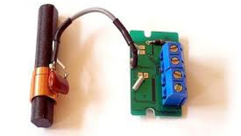
The inductance of the power supply on the PCB is generally wound on a circular magnetic core coated with various colors with a very thick enameled wire. In addition, there are usually several tall filtering aluminum electrolytic capacitors nearby, which are classic LC filter circuits. In addition, the PCB also uses a large number of serpentine wires and chip tantalum capacitors to form the LC circuit. Few people notice that when designing LC circuits, the snake wire is folded back and forth across the board and can also be seen as a small inductor.
In short, the principle of the LC filter circuit is actually the combination of the basic characteristics of the L and C components. Because the capacitive reactance of the capacitor xc=2nfc will decrease with the increase of the signal frequency, and the inductance of the inductor xl=2f will increase with the increase of the signal frequency. If capacitors and inductors are connected in series, parallel, or mixed, their combined impedance can also vary greatly with the frequency of the signal. This shows that different filter circuits will present a large or small reactance to a certain frequency signal so that the frequency signal can pass or be blocked. Therefore, the filter circuit plays the role of selecting a certain frequency signal and filtering out a certain frequency signal.
Have a further insight into the LC circuit.