

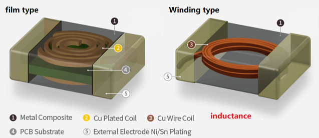
Coils wound into a spiral shape are inductive. Coils used for electrical purposes are called inductors. Inductors are widely used in electronic circuits and can be divided into two categories. One is the inductance used in signal systems. Another category is power inductors used in power systems.
The inductor is a very common component, and it is easy to be ignored by some of its basic parameters, resulting in insufficient design and serious product use problems.
The more detailed things are, the more worthy of careful scrutiny. This is the basic skill of hardware engineers.
The following takes the power inductor as an example to introduce the basic parameters of the inductor.
1 Inductance value
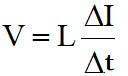
Inductance value The basic parameter of the inductance is also an important parameter that affects the ripple current and load response. Inductance and capacitance are dual components, and the inductance has one of the most important and most basic formulas:
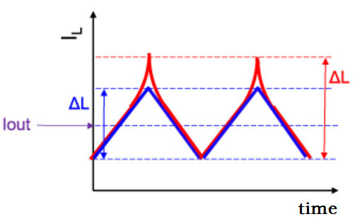
The current flowing through the power inductor in a DC-DC converter is a triangular wave current. Generally speaking, the ripple current ΔI can be set to about 30% of the load current Iout. Therefore, as long as the conditions of the DC-DC converter are determined, the appropriate power inductor inductance can be roughly calculated according to the following formula.
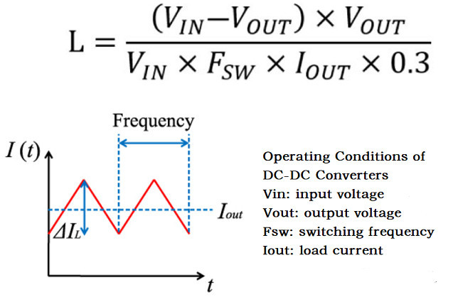
Different inductance values are recommended as reference values in the SPEC or datasheet of the DC-DC converter. Therefore, even if you do not perform calculations such as the above formula, you can still select the reference value according to the manufacturer. If you want to replace the new inductor model, its parameters should not be too far from the reference value recommended by the supplier.
2 Saturation current Isat
The saturation current characteristic is also called the DC superposition characteristic, which affects the effective inductance value of the inductance during operation. If the selection is not appropriate, the inductance is easy to saturate, causing the actual inductance value to drop, which cannot meet the design requirements, and may even burn out the circuit. The definition of saturation circuit is slightly different. Generally speaking, it refers to the current when the initial inductance value is reduced by 30%. uH. If Isat is not enough, the ripple current will increase as the inductance value decreases. Because according to the above formula, when the load current is constant, L decreases, and I naturally increases.
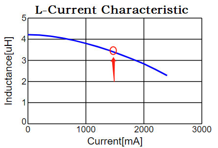
Special note: If this parameter is not selected properly, it is likely to cause an increase in the output current ripple, which in turn leads to an increase in the peak current, resulting in a decrease in the inductance value, which further increases the output current ripple, resulting in a vicious cycle of travel.
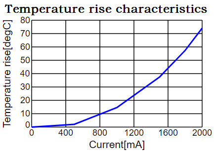
3 Temperature rise current IItemp
This is a parameter that specifies the allowable range of ambient temperature when using an inductor. The definition of temperature rise current varies from manufacturer to manufacturer. Generally speaking, it refers to the circuit when the temperature of the inductor is raised by 30°C. The effect of temperature varies depending on the operating environment of the circuit, so select it after considering the actual operating environment.
4 DC impedance Rdc
Indicates the resistance value when passing direct current. The biggest and most direct influence of this parameter is the heating loss, so the smaller the DC impedance, the less the loss. Reducing Rdc is slightly conflicting with conditions such as size miniaturization. It is sufficient to select a product with a smaller Rdc from among the above-mentioned inductors that satisfy the necessary characteristics such as inductance and rated current.
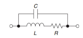
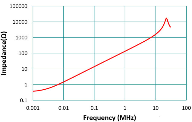
5 Impedance frequency characteristics
The impedance of an ideal inductor increases as the frequency increases. However, due to the existence of parasitic capacitance and parasitic resistance, the actual inductance is inductive at a certain frequency, and capacitive when it exceeds a certain frequency. On the contrary, the impedance decreases with the increase of frequency. This frequency is the turning frequency.
The above are the characteristic parameters related to the inductor, and each parameter must be carefully evaluated when selecting an inductor.


